

Accurate wind data starts with a properly calibrated instrument. Whether you’re supporting a national weather service, conducting climate research, or optimizing a wind energy site, the quality of your measurements depends entirely on the precision of your sensors—and that precision requires consistent, disciplined calibration.
R.M. Young Company has spent over 60 years designing and calibrating meteorological instruments that perform in the most demanding environments on Earth. Here’s an inside look at exactly how we calibrate the Wind Monitor before it leaves our facility, how you can verify that accuracy in the field, and what your options are when a sensor needs a deeper check.
Wind Direction Calibration: Testing the Potentiometer
The wind direction sensor uses a precision potentiometer to convert the physical rotation of the wind vane into a proportional electrical signal. Our specification for the Wind Monitor is ±3° of accuracy across the full measurement range—a standard we validate on every unit before it ships.
Our Calibration Process
Each wind monitor goes onto a dedicated azimuth calibration fixture that lets us precisely control and measure the angle of the sensor. We apply the excitation voltage, zero the range using a calibrated thumbwheel, and generate a graph of the output signal at each point. That graph tells us immediately whether the potentiometer is performing within specification.
Understanding the Dead Band
One characteristic of potentiometer-based sensors worth understanding is the dead band. Every potentiometer has a physical seam—a small angular zone of roughly 5° where the output can’t be guaranteed to the same accuracy standard.
This is not a defect. It’s an inherent characteristic of the design. Our usable measurement range is 0 to 355°, and we guarantee ±3° accuracy anywhere within that span. If you know where your dead band falls during installation, you can orient it away from your prevailing wind direction and it will never affect your data.
Wind Speed Calibration: Testing the Magnetic Sensor
Wind speed in the Wind Monitor is measured using magnetic induction: a magnet mounted to the rotating anemometer passes over a fixed coil, generating an AC sine wave signal. The amplitude of that signal scales linearly with rotational speed, which makes calibration both straightforward and highly reliable.
What We Test and Why Linearity Matters
We calibrate wind speed output by driving the sensor at a precisely controlled RPM and measuring the frequency of the sine wave produced. Because the relationship between rotational speed and frequency is linear, a validated low-speed check confirms performance across the full operating range. That predictable linearity is what makes our instruments reliable for long-term, unattended deployments in remote and extreme environments.
A Note on Capacitive Loading
When a capacitor is placed in parallel across the sensor outputs—as some signal conditioning circuits require—the linear relationship holds only up to a certain speed threshold. Beyond that point, the magnet rotates too fast for the capacitor to fully charge between cycles, which compresses the output signal. Our standard calibration is performed without a capacitor in-line, establishing a clean baseline that integrators can work from when designing their signal conditioning.
How to Verify Calibration in the Field
Factory calibration doesn’t expire the moment a sensor ships—but it does need to be verified on a regular schedule to stay trustworthy. YOUNG recommends tower checks every 6 months for operational accuracy (±0.5 m/s, ±5°) and every 3 months for research-grade accuracy (±0.3 m/s, ±3°). Always perform a check at initial installation.
Verifying Wind Direction Accuracy
Apply the rated excitation voltage to the sensor—typically 3.5V DC for most Wind Monitor models. Output voltage scales linearly with angle, so expected values are straightforward to calculate: at 180°, for example, you should read approximately half the excitation voltage. Step through multiple reference angles across the 355° range and compare each output to your established calibration record. Any deviation greater than ±3° means the sensor is out of specification and should be returned for service or recalibration.
Verifying Wind Speed Output
Remove the propeller or cup wheel and drive the shaft at a known RPM using a controlled drive unit. Measure the output signal and compare it to your calibration curve. A measurable, proportional output at a mid-range RPM confirms the transducer is functioning correctly.
Checking Bearing Condition
Bearing wear is one of the most common—and most overlooked—sources of sensor error. Worn bearings increase drag, raise the starting threshold, and reduce sensitivity in light-wind conditions. A simple torque check catches this before it compounds into a data problem: if the anemometer or vane fails to rotate under a known applied torque, the bearing drag has exceeded your threshold limit and the sensor needs service.
YOUNG Calibration Accessories
If you’re performing these checks yourself, we offer a complete line of calibration accessories built specifically for our sensors:
- Models 18802 / 18811 Anemometer Drives — Rotate the anemometer shaft at a precisely controlled RPM (200–15,000 RPM for propeller sensors; 20–990 RPM for cup anemometers) for wind speed output verification
- Models 18112 / 18212 Vane Angle Fixtures — Bench-top and tower-mount fixtures for systematic wind direction signal checks at ½° resolution
- Models 18310 / 18312 Torque Discs — Pass/fail bearing checks for propeller and cup anemometers, with weighted discs calibrated to specific threshold torque values
- Model 18331 Vane Torque Gauge — Slips directly over the Wind Monitor housing for fast, accurate vane bearing checks
- Model 18301 Vane Alignment Rod — Visual alignment aid for orienting the vane to a known reference direction at installation
These accessories won’t replace a wind tunnel, but they give you a reliable, repeatable way to monitor sensor health between factory calibrations and catch problems before they affect your data.
Browse Wind Sensor Calibration Accessories →
When to Send Your Sensor Back: NIST Traceable Calibration
Field checks verify that your sensor is still performing within specification. They don’t re-establish the calibration baseline. For that, you need a controlled environment—and that’s where our in-house calibration service comes in.
Wind Tunnel Calibration
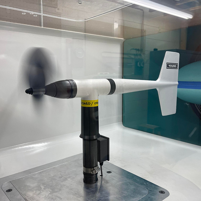
YOUNG performs NIST traceable wind sensor calibration in a 50 cm × 76 cm open-return wind tunnel. Each calibration covers 14 test points from 0 to 30 m/s, producing a full calibration report with data. This is the standard for research-grade accuracy requirements and any application where documented traceability matters—regulatory compliance, long-term climate monitoring, or data that will be submitted for peer review.
Standard Calibration
All YOUNG sensors—new or returned—receive a Standard Calibration prior to shipment, verified to be within specified tolerances. A calibration certificate is issued at the time of shipment. If your application doesn’t require full NIST traceability, Standard Calibration is a cost-effective way to re-baseline a sensor after extended deployment.
Why Annual Calibration Matters
Every instrument we ship leaves our facility within specification. But calibration is not a one-time event.
Potentiometers drift. Resistive elements change with age. Temperature cycling, humidity, and electrical aging all cause the resistance curve to shift gradually—subtly enough to escape a visual inspection, but meaningfully enough to affect your data. A sensor that was accurate at deployment may be reading 4–5° off two or three years later with no visible sign of damage. The only way to catch this is to measure it.
Bearings wear. Vanes pick up small dings from debris. Cup anemometers accumulate contamination over years of outdoor exposure. Any of these can increase drag and reduce sensitivity in light-wind conditions. Catching a bearing problem early means a simple, low-cost fix. Catching it after years of degraded data is a much harder conversation.
Harsh environments accelerate everything. Coastal salt, high-elevation UV, industrial particulates, and freeze-thaw cycles all shorten the interval between meaningful performance changes. In these applications, don’t wait for the annual cycle if you have any reason to suspect performance has changed.
Your data is only as good as your calibration record. For research, climate monitoring, and regulatory compliance, the ability to prove data accuracy matters as much as the accuracy itself. An annual calibration log creates a documented chain of accuracy that supports your work under review. Without it, you’re relying on the assumption that nothing changed—which is not a position most researchers or regulators are comfortable with.
The Bottom Line
Calibration is not maintenance overhead. It’s the foundation of trustworthy measurement. The quality of environmental decisions—from storm warnings to turbine siting to pollution dispersion modeling—depends entirely on the accuracy of the data feeding those decisions.
A yearly field check takes a few hours with the right tools. NIST traceable recalibration, when it’s time, gives you a documented baseline you can stand behind. The cost of skipping either, in bad data, repeated work, or compromised research, is almost always much higher.
Questions about calibration intervals, accessories, or sending a sensor in for service? Contact our support team—you’ll reach a real person within 24 hours.